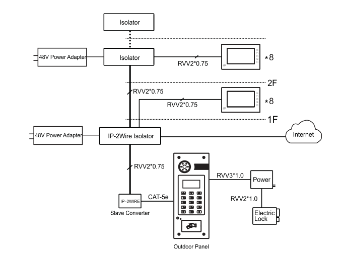
The Ilsolators are used to extend the Ethernet IP signals via 2Wire cable in the existing 2Wire network of building.
The apartment type of 290 2Wire SIP door phone system can constitute cable structures for all kinds of units. Use digital devices as the terminals and make networking of 2-wire system via intermediate equipment. Bi-directional data penetration of IP and two-wire systems can be realized between devices.
This system is suited for transformation project of old buildings which can remain 2Wire cables. It can save troubles of cable wiring and infrastructure rebuilding as well as, reduce the cost of projects.
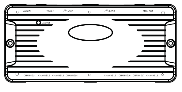
290A(2Wire IP Isolator):

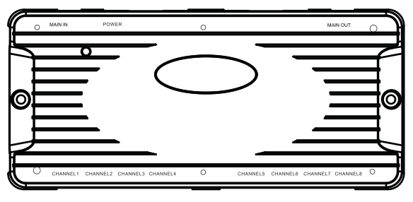
290AB(Isolator):

Voltage: DC 48V
Rated power: 4W(290A)/2W(290AB)
Max connection:
Every 290A or 290AB support 60W power and connection to max 8 indoor monitors.
Distance: 100m, if there is cascade connection with 290AB, it can connect to max 24 indoor monitors.
50m, if there is cascade connection with 290AB, it can connect to max 32 indoor monitors.
Note: If more than 32 indoor monitors are required, please call DNAKE tech-supporting and customer center.
Step 1. Hardware Check and Preparation
●Please check if there is any product defect.
●Prepare :
1) Network cable
2) 2Wire cable
3) 48VDC Power supply to 290A or 290AB.( Please check the cable length, spec, and connection status.)
4) 2.0/2.5mm Slot Screw Driver.
Step 2. Installation
●In general, 290A is set in weak power box on the first floor. Every unit has only one 290A to realize the function of management.
●Interface "Main In" is connected to outdoor panel and interface "Main Out" is used for cascade expansion of 290AB. Two network interfaces have switch function and support networking.
●Connect a 48V DC power supply into 290A or 290AB to provide power to the sub-system, including the outdoor panel and indoor monitor.
●AIll devices are in 2Wire Link Mode. They will find each other and establish basic level encrypted communication.
290A provides green and red LEDs to indicate the status of Link/Act.
1.Red LED means the connection status of 2-wire cable. If the red LED is always on, it means 2Wire Link Mode. If the LED flashes slowly, it means 2Wire Unlink Mode.
2.Green LED is the Ethernet connection indicator. When the module is transmitting or receiving through Ethernet, the LED toggles with 250ms period.