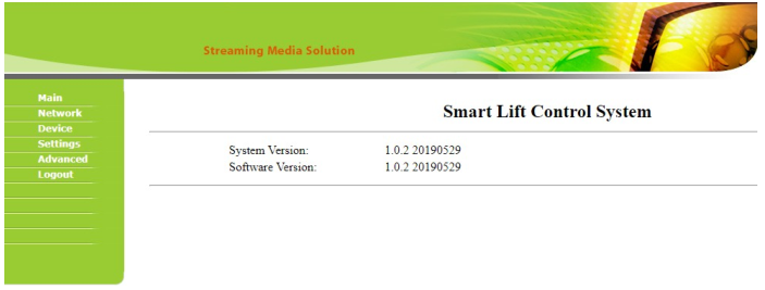
The system and software information:
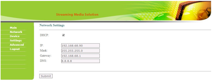
Network Settings:
DHCP: enable / disable DHCP function
IP: IP address should be unique in the same network
Mask: according to the actual network situation
Gateway: according to the actual network situation
DNS: according to the actual network situation
Click the submit button to complete parameter modification:
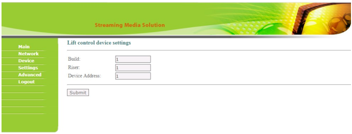
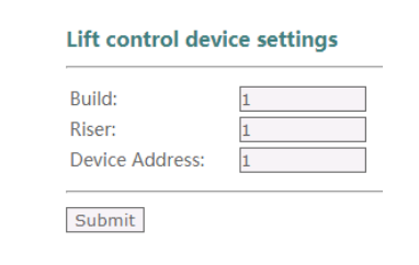
Lift control device settings:
Build: Building number of EVC ( the same with the outdoor panel which is used
together.),range 1~999
Riser: Unit number of EVC,range 0~99
Device Address: range 0~98
Click the submit button to complete parameter modification:
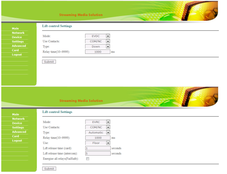
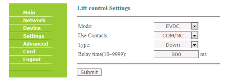
Lift control Settings:
Mode: Working mode EVRC or EVDC
EVRC:Usually used to control the internal call panel of elevator
Use contacts:Choose the type of contacts
Type:Control down and up key of lift’s external call panel,or only control down key
of lift’s external call panel
Relay time:The default time is 500ms,which is used to stimulate the time of
pressing up and down key.
EVDC:Usually used to control the external panel of elevator
Select the EVRC/EVDC mode and click the submit button, the corresponding parameter
setting interface will appear.
Use contacts:Choose the type of contacts
Type:Control Automatically or Control Manually
Use:Configure the settings based on Floor and Apartment
Lift release time (card):The duration of triggering with card
Lift release time (intercom): The duration of triggering via intercom
Energise all relays(FailSafe):if you want the relay status to be opposite when
power it,enable it,if not,leave it alone. (Usage: On EVRC mode of the elevator
module, when you enable this option, you can use the NC port of the relays as an NO
port to connect the Floor buttons inside the elevator. In this way, the module in the
case of failure or power will not affect the normal use of the elevator.)
8.4.1 EVRC mode
Lift release time (card): 0~9999 (default 5s)seconds
Lift release time (intercom):0~9999 (default 1s)seconds
use Contacts COM/NO:When receiving the corresponding trigger command, the
normally-open (NO) relay will activate.
use Contacts COM/NC:When receiving the corresponding trigger command, the
normally-closed (NC) relay will activate.
Type:Control Automatically or Control Manually
Use:Configure the settings based on Floor and Apartment
Energise all relays(FailSafe):
When EVC enables this function, all relays are in the opposite state.
When EVC is Powered on with this function enabled,all relays are in the opposite
state. use Contacts COM/NO:When receiving the corresponding trigger command, the
normally-closed (NC) relay will activate.
use Contacts COM/NC:When receiving the corresponding trigger command, the
normally-open (NO) relay will activate.
The relay will be restored to its original state after Power OFF.
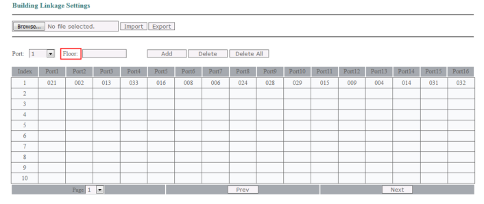
If “Use” at “Settings” is configured as “Floor”,you will see “Advanced” as follow:
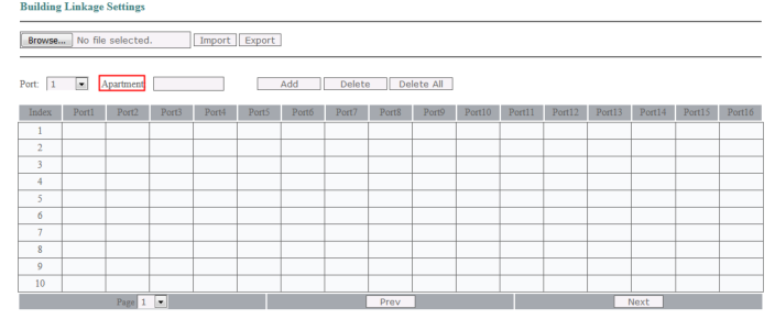
If“Use”at “Settings”is configured as“Apartment”,you will see “Advanced "as follow:
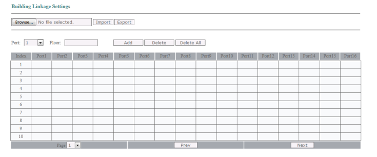
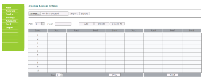
When“Type” is configured as“Automatic”,the table will display as follow. In this
configuration,the two relays at lift controller will be triggered at the same time,B1 and
B9,B2 and B10,B3 and B11…will be triggered in pairs at the same time.

Select button: Setting Upload File Path
Import: After setting the file path, click Import to upload the file.Only support “.csv”format file.

Export: Export configuration file (.csv)
Port: Select port 1~16(B1~B16)
Floor/Apartment: Support 1 to 4 digits that is the same as the indoor monitor’s room
number
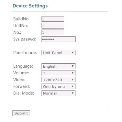
For Example:
Indoor Monitor
IP Address: 192.168.98.190
Building Number: 1
Unit: 1
Room: 101
Device: 0
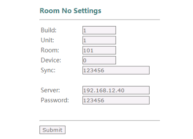
Outdoor Panel:
IP Address: 192.168.98.54
Building: 1
Unit: 1
EVC Module:
IP Address:192.168.98.231
Building:1
Riser(Unit):1
when“Type” is configured as“Manual”,the EVC relay Port1 (B1) normally-open contact
will work,and visitors can press the floor button he want to visit,in this example,he will
have access to press floor 1;When“Type“ is configured as“Automatic”, the EVC relay
Port1 (B1) and Port9 (B9) normally-open contact will work at the same time,vistors no
need to do any operation.
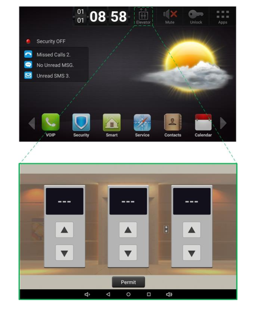
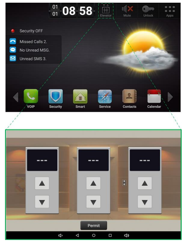
Permit button: Permission to open the floor where the indoor monitor is located
8.4.2 EVDC mode(Type: only control Down Button of elevator )
Parameter settings are the same as EVRC.
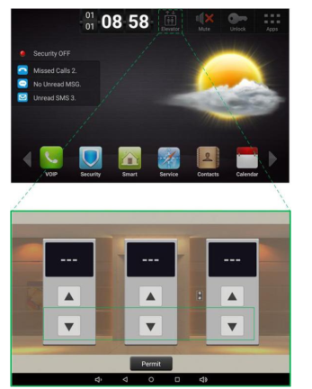
Click indoor monitor Elevator icon(only Down button enable) , the EVC relay Port1 (B1)
normally-open contact will work.
8.4.3 EVDC mode(Type: control UP & Down Buttons of elevator )
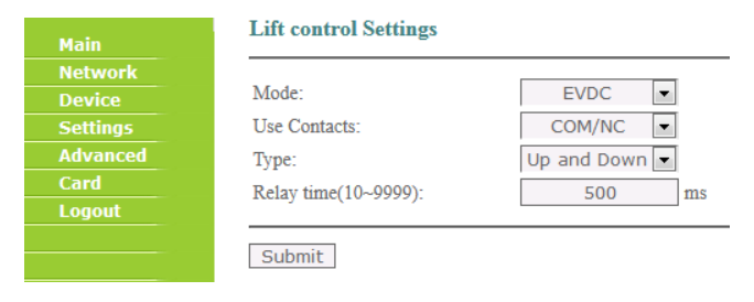
Parameter settings are the same as EVRC.
Click indoor monitor Elevator icon(Down button) , the EVC relay Port1 (B1) normally-
open contact will work.
Click indoor monitor Elevator icon(UP button) , the EVC relay Port9 (B9) normally-open
contact will work.
Note:
Port 1(B1) corresponds to port 9(B9)
Port 2(B2) corresponds to port 10(B10)
Port 3(B3) corresponds to port 11(B11)
Port 4(B4) corresponds to port 12(B12)
Port 5(B5) corresponds to port 13(B13)
Port 6(B6) corresponds to port 14(B14)
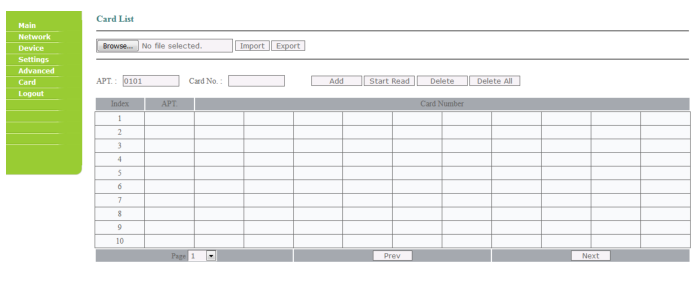
The controller supports to connect with a card reader via RS485 to realize that the residents can swipe their fobs at lift car to call the lift/elevator,and the controller will provide access to the floor where the fobs are bound with.
You can Export and Import the card list here,and also Add the fobs/cards here manually and automatically.
If you want to Add the fobs/cards automatically,pls make sure the controller and card reader is connected correctly,and then press “Start read” to start reading card No.,swipe the fob/card above card reader,a card adding interface will come out automatically,you can only input apartment No.,then press “Add” to add this card to the card list.
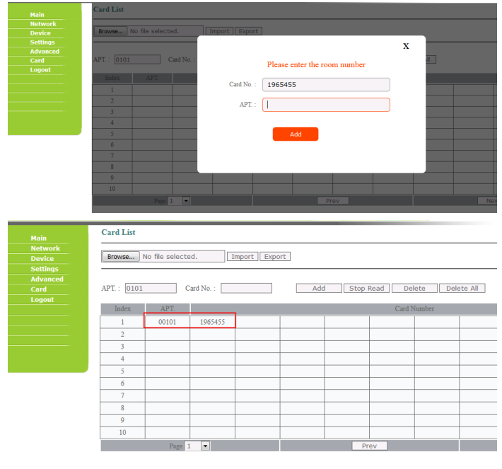
Note:1. The card list only works at “EVRC” mode.
2.Make sure the RS485 port is existing at the controller,because some old version doesnot support RS485 now,because some components are not patched before.
